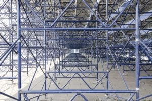
Have you ever wondered why a scaffold can support loads? Have you ever wondered how an engineer can determine what a scaffold leg can support? Do you wonder who thought up the way to answer those questions? Wonder no more. Thanks to Swiss physicist Leonhard Euler, (typically pronounced “Oiler”), a method was developed to determine the strength of a column (which is what a scaffold leg is). Back in 1774, Mr. Euler discovered that a column would not buckle until the load reached a certain amount. This load, known both as the critical force and also as Euler’s Load, is affected by certain characteristics of the column. These characteristics include the support conditions at the end of the column, the distance, or length, between support points, the shape of the column, and the material of the column. Based on these parameters, Mr. Euler developed a formula that determined the critical load.
While scaffolds can be manufactured using a variety of materials, steel is the most common material used. (Euler’s equation can be used with any material, including aluminum, fiberglass, plastic, and wood.) Scaffolding is typically constructed with round tube, which is equally strong in all directions. Second to a round tube is a square tube which exhibits similar qualities. Rectangular tube may be used but the strength will be higher in the direction of the long face of the tube compared to the short face. Other shapes may be used if the manufacturer determines that there may be an advantage. While the shape of the material, and the material itself will help determine the capacity of a particular scaffold leg load, the characteristic that affects the strength of scaffolds more than the material or shape is the distance between points of support. Depending on the scaffold type, these points of support may be cross braces, diagonal braces, horizontal braces, or ties to an existing substantial structure. For example, in a tube and coupler scaffold, the length between points of support is usually 6’-6”. The horizontal members and the diagonal members are connected to the legs at these intervals. Therefore the length of the scaffold leg (column) is 6’-6”. For a systems scaffold, the support points will occur where the horizontal and diagonal members are attached to the leg. This usually occurs at 6’-6” to 7’-0”, similar to a tube and coupler scaffold. A frame scaffold, on the other hand, will have points of support at the cross brace studs in one direction, and at the location of the horizontal members that are welded to the legs in the other direction.
The distance between the points of support are critical to the strength of the scaffold leg. Reducing the distance between the horizontal members on a tube and coupler scaffold or systems scaffold by 50 per cent can more than double the strength of the scaffold leg. Conversely, increasing the distance between horizontal members by 50 per cent, (not recommended,) can reduce the capacity by substantially more than 50 per cent. Therefore, if one is to deviate from the standard erection procedures, it is important to verify the design prior to construction. Similarly, removing a critical cross brace from a frame scaffold can drastically reduce the capacity of the scaffold. This is not to say that braces cannot be removed. A frame scaffold will have sufficient bracing as long as the scaffold leg is braced to at least one other leg. However, removing the incorrect brace may result in a scaffold that is unable to provide the anticipated support. This is not good!
Frame scaffolds also differ from tube and coupler, systems, and wood pole scaffolds in another aspect in that additional bracing is provided by the horizontal members that are welded into the frame. Since this bracing varies between frame styles and manufacturers, all frames are not equal in capacity. In fact, a review of scaffold load charts will show that frame capacities vary dramatically, depending on the height of the frame, the location and spacing of the brace studs, and the pattern of the frame horizontal members.
Mr. Euler’s formula has been used successfully for quite a long time. Other formulae have been developed since Mr. Euler’s work and refinements have been made to these formulae so engineers can accurately predict the capacities of columns under a broad range of circumstances. But keep in mind that the basic premise is still accurate: The capacity of a scaffold leg can be easily affected by modification of the distance between support points. If you cannot accurately determine the effects these modifications will make, don’t modify the scaffold. Don’t mess with Mr. Euler’s formula!


